-
Suitability of SolidWorks as a tool for 3D Solid Modelling – Build-A-Bow
Jonathan Kah
15/10/2017
1. Introduction
SolidWorks, by Dassault Systèmes, is an established and reputable application within the computer aided design (CAD) industry. It is most commonly used for designing and modelling mechanical systems, and one needs not look further than the Internet to find a vast array of content showcasing its capabilities. Because of this, I have been tasked by Build-A-Bow to investigate the suitability of SolidWorks as a CAD tool to design an arrow. This report will detail its suitability, in terms of ease of use and capability, to create complex features within the arrow. It will also discuss my experience working with this software, the model I was able to create and features of interest to the company.
2. Design and Modelling
2.1 Arrowhead
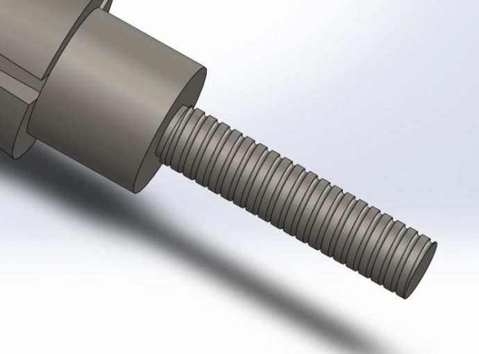
This part was created with an extrude and revolve. A circular pattern was used to cut the slots, for the arrow blades to go in. Then, an extruded cut was made to thin down the end where the screw thread is (with one extra thinner section for thread relief), and the other end for the arrow point to attach to. A helical swept cut was used to create the thread (Figure 1), by defining a circle as a cutting tool, and sweeping it along a spiral. This helical sweep/swept cut is essential in any CAD tool, as screws with threads are prevalent in almost every single mechanical device. See Figure A-1 for the completed part.
Figure 1: Close up of helical thread
2.2 Arrow connector, blades and point
All three of these parts were very simple to model. Firstly, the connector sleeve (Figure A-2) that joins the arrowhead to the shaft was a trivial extrude of two circles set within each other. This was the simplest part of the assembly to model, and was merely an exercise in making the model realistic.
Each blade (Figure A-3) was just an extrude of a sketch, with a chamfer on the cutting edge. This was used to test the “offset entity” feature in drawing a sketch. This allows an entity to be copied and enlarged, keeping a constant offset of an input distance in between the two entities. This is a great feature and has many potential applications for 3D solid modelling a bow and arrow/accessories, such as rings on a target on the firing range, or in the sketch of the connector sleeve mentioned above.
Lastly, the point of the arrow (Figure A-4) is a revolve of only one simple sketch. I chose to model a simpler part to test the changing of dimensions through VBA in the Excel sheet – the length of the point was chosen for this purpose.
2.3 Arrow shaft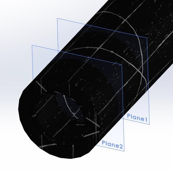
The next part of the model was the shaft of the arrow (Figure A-5). I also chose this part to implement a changing dimension from the Excel sheet. Firstly, I revolved a slightly more complicated sketch to form the main body, including a hole for the arrowhead to screw into, and a hole at the other end for the arrow nock to click into. A helical sweep was used to create the internal thread that complements the thread on the arrowhead. Edge fillets were used to round off the bottom of the internal holes.
Since the length of the shaft is able to change, the ribbing that holds the nock in place will also have to change. Although this could have been done in the original sketch for the revolve, I decided to test the reference geometry tool, by creating planes with offset distance from the end of the part (Figure 2). Sketches were then created on these planes and swept around the inside of the nock hole.
Figure 2: Distance offset planes
2.4 Arrow fletching
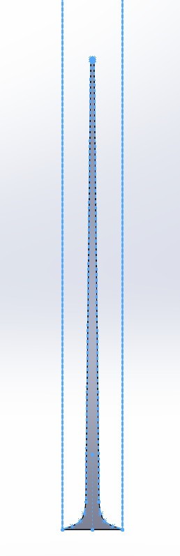
This part (Figure A-6) was used to test the loft function. I attempted to define five rectangular-elliptical-point cross sections on as many parallel planes to loft through, starting from the rectangle at the bottom and reaching up to a point. However, since the top of the vane is a point, it does not satisfy the requirement for a loft to have the same number of corner points in every sketch. To get around this, I simply created a block to cut off parts which were not required. A spline sketch was used to outline the shape of the vane parallel to the arrow’s flight path, then an extruded cut was used to remove the excess material. Another spline sketch with mirrored entities (Figure 3) defined the profile of the vane perpendicular to the flight path, and another extruded cut was used to cut off excess material.
Finally, an extrusion was made from the bottom of the shape. A circle with diameter of half the arrow diameter (this will be covered below) was used to cut away material so that the remaining part would be able to mate with a coincident constraint to the arrow shaft.
This was all done to half scale, to test the scaling function offered by SolidWorks. When the object was scaled about the centroid (of mass), changes were made to parts that were referenced, leading to dangling dimensions and a failed rebuild. However, scaling about the origin did not raise any of these errors (since one corner of my sketch was on the origin). If the part was not cornered on the origin, this error of dangling dimensions may become a problem again.
Figure 3: Splined profile
2.5 Arrow nock
 The arrow nock (Figure A-7) was by far the most complicated part – since it was my final part to the model assembly, I wanted to use as many new features as possible, to report back on to the company.
Firstly, an extrude was used to make the base cylinder. Then a triangle was used as a cutting tool for a revolved cut, to create the taper of the part.
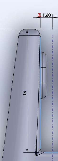
An extruded cut was used to make the notch where the bowstring will go, when firing the arrow. The depth of the notch is another dimension able to be changed by the VBA, and drives another dimension – the width of the notch. This was achieved by using an equation which set the overall width to be one fifth of the depth. In the sketch, this was modelled by a half rectangle with length ð‘™ input by VBA, and width 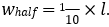 . A reference axis was
created down the centre of the cylinder, and this was used to reflect the half rectangle to form the full sketch with width 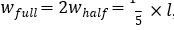 , with the mirror entity sketch tool (Figure 4). From the faces created by the extruded cut, the grips which grip the string were extruded from a slot sketch.
The next step was to create the grips that connect to the ribbing on the inside of the arrow shaft. This involved projecting a 2D sketch onto the surface of the cylinder, and converting that entity to a 3D sketch. A construction line normal to the sketch was created, and the boss tool was used to extrude off the curved surface; then the chamfer tool was used to cut the edges off. This body was then made into a circular pattern around the cylinder, with six bodies at equal spacing from each other. The process was then repeated to create another set of six grips, slightly higher up the nock.
Figure 4: Notch depth vs width with reference axis
After that, a cut needed to be made to remove some excess material. I created a reference axis, then a reference plane Plane 2 at an angle offset from the top plane, about the axis. Another plane Plane 3 was set to be a distance offset from Plane 2 – it was from Plane 3 I extruded a sketch to cut away some material from the nock.
Finally, edge and face fillets were used to smooth the edges.
2.6 Assembly
The assembly is where all the parts are put together into one model. I started with the arrowhead, constraining the point and blades into coincident relationships with it, in their respective slots. Next was the screw thread between the arrowhead and the shaft – I constrained it such that they locked together. The connecting sleeve was a simple coincident relationship with the head.
For the vanes, I constrained it so the base was coincident to the arrow shaft, and used a distance offset from the end of the arrow. I then used the circular pattern tool to define the number of vanes – this is also a value that the VBA code will change. Finally, the nock was mated such that it is slotted all the way in, and the ribs line up with the grips.
3. Prominent aspects
- Drawings are a key part of any design process – without them, parts can’t go to manufacture. SolidWorks has an integrated environment used to create these. A drawing of the arrow_head part can be seen in Figure A-8.
- The equations, as mentioned earlier, allow for variables to be “driven” by driving variables (those that control other dimensions).
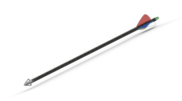
- The ability to render is wonderful, allowing the user to be able to view the final product before it is ordered (Figure 5).
- Smart Dimension is an amazing tool that allows the user to easily dimension any relationships or lengths within a sketch.
Perhaps the most important was the ability to use VBA through Excel to modify dimensions and parameters in the model. Our order form is the basis for the specifications in the build of the bow and arrow; hence they must transfer to the design as effortlessly as possible. Thus, I integrated a subroutine in the data sheet which updates some of the dimensions of the arrow SolidWorks model when the user clicks the “Update SolidWorks Assembly” button. See Appendix B for a full listing of VB code used in this project.
Figure 5: Full render of assembly
This button will update four things: point length, shaft length, number of vanes, and notch depth. The point length was altered by simply opening the arrow_point document, and setting the variable Point_length@Sketch1 to be equal to the value given in the SolidWorks table.
Shaft length and notch depth were similar – however, since notch depth was a driving variable, the width of the notch also changed when this was updated. The name of the variable used to define the circular pattern used for the vanes could not be altered, resulting in an ugly name “D1@LocalCirPattern1”. This is my only gripe about this software package.
One of the strengths of this is that it allows the customer to change their order and view the results of it almost immediately. The automatic dimension changes and detail updates requires no technical knowledge from the user at all – just an order on the type of arrow.
4. Learning experience
It is important to detail the problems encountered using SolidWorks (as well as eventual solutions), to assess its ease of use as a CAD tool.
The earliest parts constructed were only dimensioned as I deemed necessary. However, as finer details were added and parts started to be added to the assembly, I quickly realised that my lazy dimensioning raised many inconsistencies and proved very frustrating. Often, other
features depended upon references to earlier parts, leading to dangling dimensions when any dimension was altered by the VBA code. This led to several iterations of dimension-fixing every time I assembled a new part – highly inefficient and very labour intensive.
The loft tool tapers two surfaces to one another. For me, it provided a significant amount of wasted time. The initial modelling stages of the vane took a long while, as I took measurements of a vane and implemented these on five different cross sectional sketches. However, as discussed above, this was not able to be completed, leading the elaborate design to be scrapped.
Another problem was my constant use of overdefined sketches. Often, the part would not highlight the error in the part constraints itself, and only display an error reading “zero thickness geometry”. Once I learnt what this error meant, fixing these became a lot easier.
5. Conclusions
I believe that SolidWorks has a smaller learning curve than our current company standard Creo Parametric – the tools seem more intuitive and are amazing. The greatest benefits are:
- The Smart Dimension feature. This is just a wonderful tool to have in your 3D CAD modelling, and definitely offers something that Creo Parametric does not.
- The ability to edit and rebuild parts from inside Microsoft Excel, through the use of VBA subroutines. The press of a single button is all it takes to build a professional model.
- The ability to implement equations to dynamically change other parts’ dimensions is extremely useful.
- The numerous useful features such as reference geometry, offset entities, and mirror entities that make sketching a lot easier.
For these reasons, I believe that SolidWorks offers a reliable platform in which an unexperienced user is able to learn quickly from. As the primary reviewer of this package, I recommend that Build-A-Bow move to SolidWorks once our license with Creo Parametric expires.
6. Appendices
6.1 Appendix A - Images
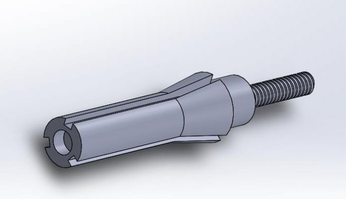
Figure A-1: Arrow head
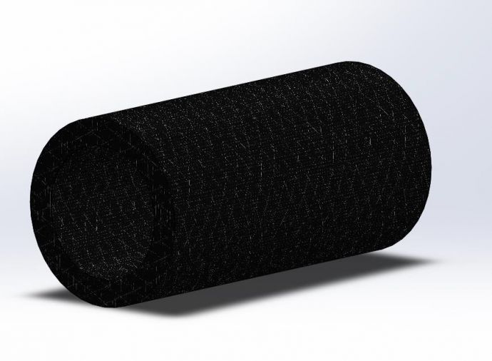
Figure A-2: Arrow connecting sleeve
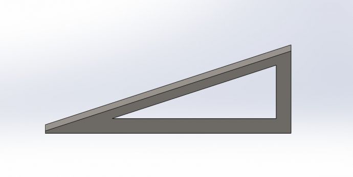
Figure A-3: Arrow blade
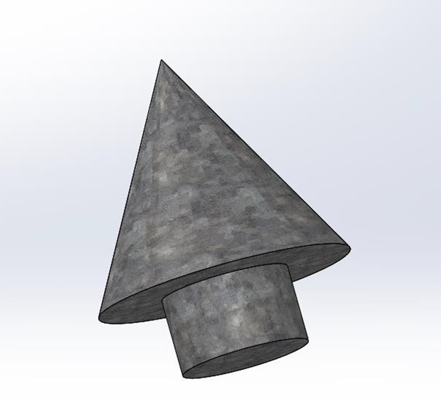
Figure A-4: Arrow point
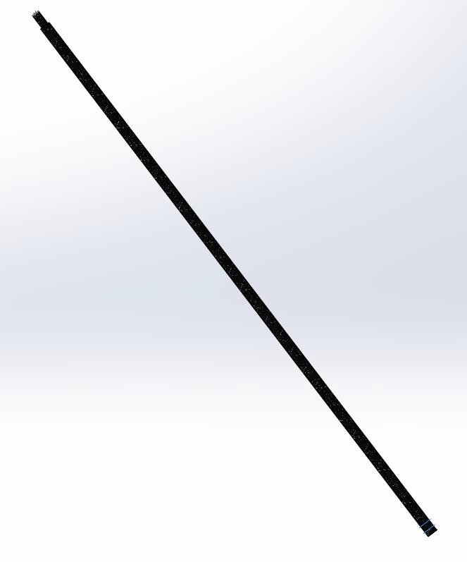
Figure A-5: Arrow shaft
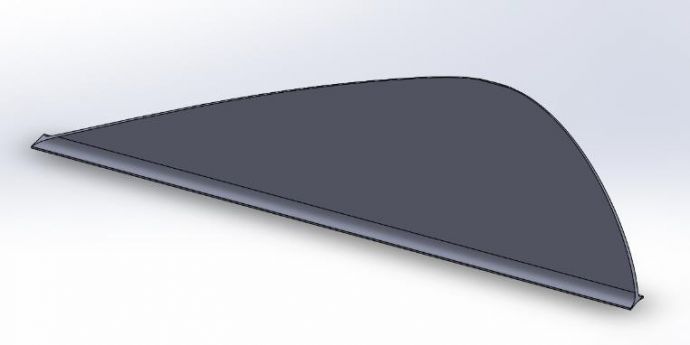
Figure A-6: Arrow fletching
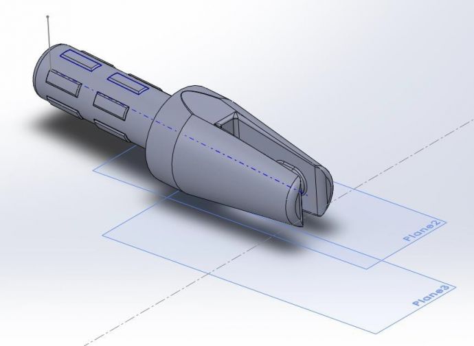
Figure A-7: Arrow nock
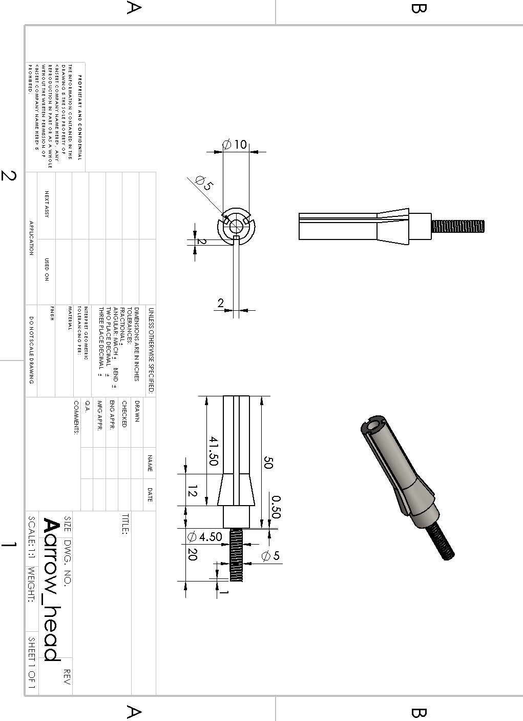
Figure A-8: Sample technical drawing
6.2 Appendix B – VB code
- Module by Jonathan Kah Option Explicit
Sub Update_SW_assembly()
- This subroutine updates the arrow in SolidWorks by calling the subs in this module.
- Then it rebuilds the assembly.
Dim swApp As Object ' Points to the SolidWorks application
Dim objPart As Object ' Points variously to solidworks parts or assemblies
Dim intResponse As Integer ' Response from user message box
Set swApp = CreateObject("Sldworks.Application") ' Create pointer to SW app
Set objPart = swApp.ActiveDoc
intResponse = MsgBox("Do you have SolidWorks running, with the arrow.asm files loaded?",
vbYesNo)
If intResponse = vbNo Then
Exit Sub
End If
Call Update_shaft
Call Update_point
Call Update_notch
Call Update_vanes
Set objPart = swApp.ActivateDoc("arrow.sldasm")
objPart.EditRebuild
End Sub
Sub Update_shaft()
- This sub uses the values stored in the "Solidworks" range of the "Data worksheet" to update the length of
- the arrow shaft and then performs a rebuild of the part.
Dim swApp As Object ' Points to the SolidWorks application
Dim objPart As Object ' Points variously to solidworks parts or assemblies
Set swApp = CreateObject("Sldworks.Application") ' Create pointer to SW app
swApp.ActivateDoc ("arrow_shaft.SLDPRT")
Set objPart = swApp.ActiveDoc
- Change the length of the arrow shaft
objPart.Parameter("Shaft_length@Sketch2").systemvalue = Worksheets("Data").Range("F34") / 1000
- Rebuild the arrow shaft objPart.EditRebuild
End Sub
Sub Update_point()
- This sub uses the values stored in the "Solidworks" range of the "Data worksheet" to update the length of
- the arrow point and then performs a rebuild of the part.
Dim swApp As Object ' Points to the SolidWorks application
Dim objPart As Object ' Points variously to solidworks parts or assemblies
Set swApp = CreateObject("Sldworks.Application") ' Create pointer to SW app
swApp.ActivateDoc ("arrow_point.SLDPRT")
Set objPart = swApp.ActiveDoc
- Change the length of the arrow point
objPart.Parameter("Point_length@Sketch1").systemvalue = Worksheets("Data").Range("F35") / 1000
- Rebuild the arrow point objPart.EditRebuild
End Sub
Sub Update_vanes()
- This sub uses the values stored in the "Solidworks" range of the "Data worksheet" to update the length of
- the arrow point and then performs a rebuild of the part
Dim swApp As Object ' Points to the SolidWorks application
Dim objPart As Object ' Points variously to solidworks parts or assemblies
Set swApp = CreateObject("Sldworks.Application") ' Create pointer to SW app
swApp.ActivateDoc ("arrow.SLDASM")
Set objPart = swApp.ActiveDoc
- Change the number of vanes
objPart.Parameter("D1@LocalCirPattern1").systemvalue = Worksheets("Data").Range("F36")
- Rebuild the vanes objPart.EditRebuild
End Sub
Sub Update_notch()
- This sub uses the values stored in the "Solidworks" range of the "Data worksheet" to update the length of
- the arrow point and then performs a rebuild of the part.
Dim swApp As Object ' Points to the SolidWorks application
Dim objPart As Object ' Points variously to solidworks parts or assemblies
Set swApp = CreateObject("Sldworks.Application") ' Create pointer to SW app
swApp.ActivateDoc ("arrow_nock.SLDPRT")
Set objPart = swApp.ActiveDoc
- Change the depth of the notch
objPart.Parameter("Notch_depth@Sketch3").systemvalue = Worksheets("Data").Range("F37") / 1000
- Rebuild the nock EditRebuild
End Sub